Aberrations
“Aberrations” is a general category including the principal factors that cause an optical system to perform differently than the ideal case. There are a number of factors that do not allow a lens to achieve its theoretical performance.
Physical aberrations
The homogeneity of optical materials and surfaces is the first requirement to achieve optimum focusing of light rays and proper image formation. Obviously, homogeneity of real materials has an upper limit determined by various factors (e.g. material inclusions), some of which cannot be eliminated. Dust and dirt are external factors that certainly degrade a lens performance and should thus be avoided as much as possible.
Spherical aberrations
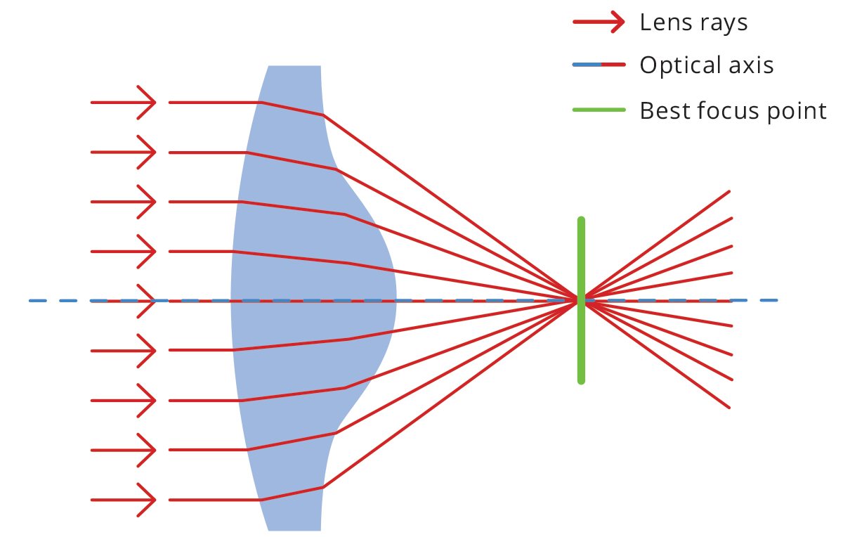
Spherical lenses are very common because they are relatively easy to
manufacture. However, the spherical shape is not ideal for perfect
imaging - in fact, collimated rays entering the lens at different
distances from the optical axis will converge to different points,
causing an overall loss of focus. Like many optical aberrations, the
blur effect increases towards the edge of the lens.
To reduce
the problem, aspherical lenses (Fig. 16) are often used - their surface
profile is not a portion of a sphere or cylinder, but rather a more
complex profile apt to minimize spherical aberrations. An alternative
solution is working at high F/#’s, so that rays entering the lens far
from the optical axis and causing spherical aberration cannot reach the
sensor.

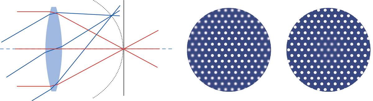
Chromatic aberration
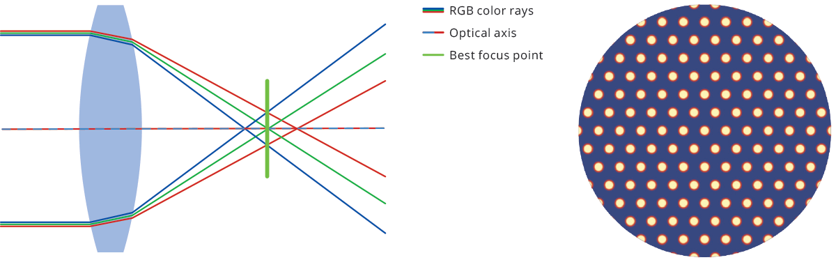
The refractive index of a material is a number that describes the
scattering angle of light passing through it – essentially how much rays
are bent or refracted - and it is a function of the wavelength of
light. As white light enters a lens, each wavelength takes a slightly
different path. This phenomenon is called dispersion and produces the
splitting of white light into its spectral components, causing chromatic
aberration. The effect is minimal at the center of the optics, growing
towards the edges.
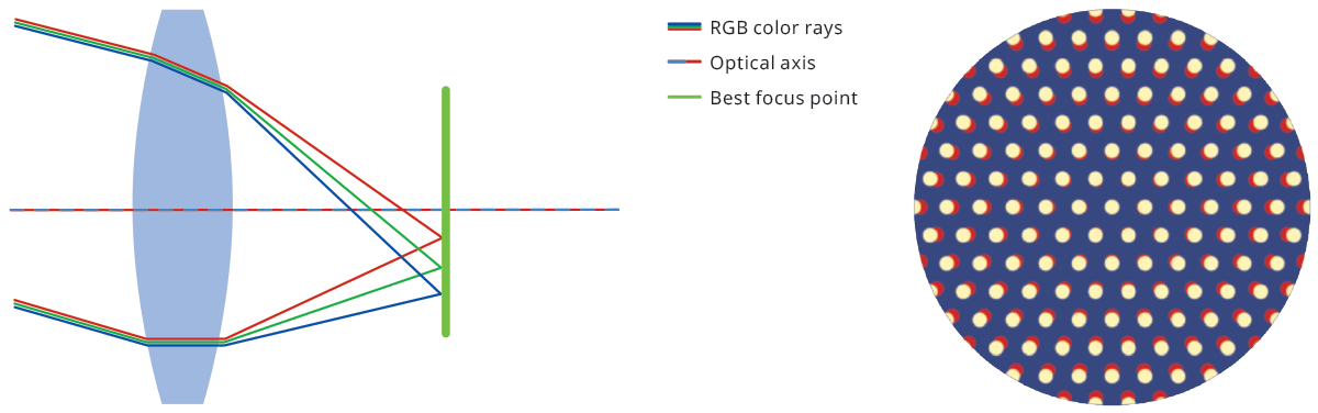
Chromatic aberration causes color fringes to appear across the image, resulting in blurred edges that make it impossible to correctly image object features. While an achromatic doublet can be used to reduce this kind of aberration, a simple solution when no color information is needed is using monochrome light. Chromatic aberration can be of two types: longitudinal (Fig. 17) and lateral (Fig. 18), depending on the direction of incoming parallel rays.
Astigmatism
Astigmatism is an optical aberration that occurs when rays lying in two perpendicular planes on the optical axis have different foci. This causes blur in one direction that is absent in the other direction. If we focus the sensor for the sagittal plane, we see circles become ellipses in the tangential direction and vice versa.
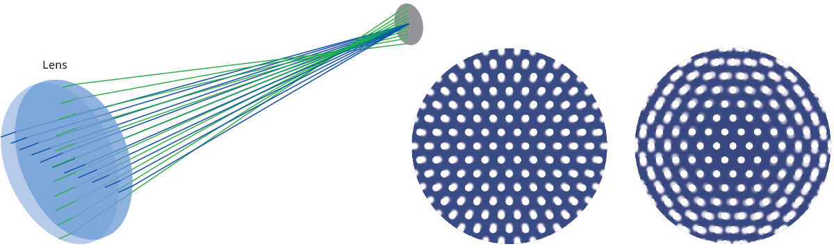
Coma
Coma aberration occurs when parallel rays entering the lens at a certain angle are brought to focus at different positions, depending on their distance from the optical axis. A circle in the object plane will appear in the image as a comet-shaped element, which gives the name to this particular aberration effect.

Field curvature
Field curvature aberration describes the fact that parallel rays
reaching the lens from different directions do not focus on a plane, but
rather on a curved surface.
This causes radial defocusing, i.e. for a given sensor position, only a circular crown will be in focus.
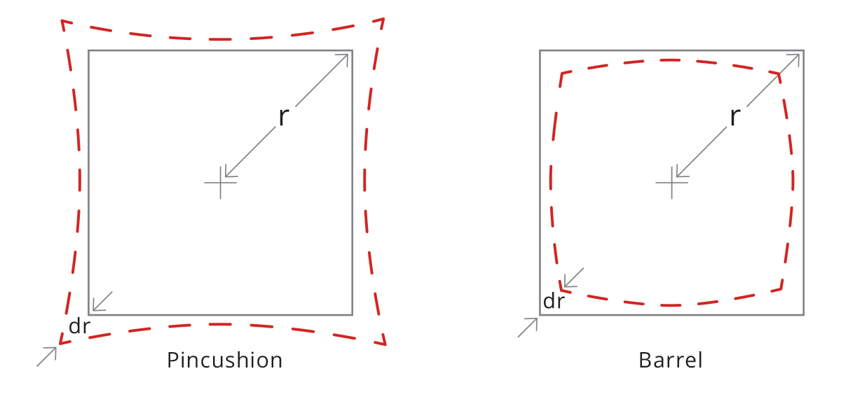
Distortion
With a perfect lens, a squared element would only be transformed in size, without affecting its geometric properties. Conversely, a real lens always introduces some geometric distortion, mostly radially symmetric (as a reflection of the radial symmetry of the optics). This radial distortion can be of two kinds: barrel and pincushion distortion. With barrel distortion, image magnification decreases with the distance from the optical axis, giving the apparent effect of the image being wrapped around a sphere. With pincushion distortion image magnification increases with the distance from the optical axis. Lines that do not pass through the center of the image are bent inwards, like the edges of a pincushion.
What about distortion correction?
Since telecentric lenses are a real-world object, they show some residual distortion which can affect measurement accuracy. Distortion is calculated as the percent difference between the real and expected image height and can be approximated by a second-order polynomial. If we define the radial distances from the image center as follows
the distortion is computed as a function of Ra:
where a, b and c are constant values that define the distortion curve behavior; note that “a” is usually zero as the distortion is usually zero at the image center. In some cases, a third-order polynomial could be required to get a perfect fit for the curve.
In addition to radial distortion, also trapezoidal distortion must be taken into account. This effect can be thought of as the perspective error due to the misalignment between optical and mechanical components, whose consequence is to transform parallel lines in object space into convergent (or divergent) lines in image space.
Such an effect, also known as “keystone” or “thin prism”, can be easily fixed by means of pretty common algorithms which compute the point where convergent bundles of lines cross each other.
An interesting aspect is that radial and trapezoidal distortion are two completely different physical phenomena, hence they can be mathematically corrected by means of two independent space transform functions that can also be applied subsequently.
An alternative (or additional) approach is to correct both distortions locally and at once: the image of a grid pattern is used to define the distortion error amount and its orientation zone by zone. The final result is a vector field where each vector associated with a specific image zone defines what correction has to be applied to the x,y coordinate measurements within the image range.
Why green light is recommended for telecentric lenses?
All lenses operating in the visible range, including Opto Engineering® telecentric lenses, are achromatized through the whole VIS spectrum. However, parameters related to the lens distortion and telecentricity are typically optimized for the wavelengths at the center of the VIS range, which is green light. Moreover, the resolution tends to be better in the green light range, where the achromatization is almost perfect. “Green” is also better than “Red” because a shorter wavelength range increases the diffraction limit of the lens and the maximum achievable resolution.