Camera link
The Camera Link standard was initially released in 2000. It is a robust, well-established communications link that standardizes the connection between cameras and frame grabbers and defines a complete interface, including provisions for data transfer, camera timing, serial communications, and real-time signaling to the camera. Camera Link is a non-packet-based protocol and remains the simplest camera/frame grabber interconnect standard. Currently, in version 2.0, the standard specification includes Mini Camera Link connectors, Power over Camera Link (PoCL), PoCL-Lite (a minimized PoCL interface supporting base configurations) and cable performance specifications.
Speed
Camera Link was built for real-time, high-speed communication. The high bandwidth of 255 Mbytes/s for one cable and up to 850 Mbytes/s for two cables assures fast transfer of images with no latency issues.
Receiver Device
Frame grabber.
Cable
Camera Link defines its own dedicated cable. Cameras and frame grabbers can be easily interchanged using the same cable. The maximum cable length is in the range of 7 to 15 meters depending on the camera clock rate.
Mini Camera
Link provides a small footprint when space is an issue.
Connectors
MDR 26-pin connector; SDR, HDR 26-pin connector (Mini Camera Link); HDR 14-pin connector (PoCL-Lite).
Camera Power Supply
Using PoCL, a PoCL camera can be powered by a PoCL frame grabber through the Camera Link cable.
Other Differentiators
Camera Link has optional GenICam support for plug and play interoperability. The use of up to two cables per camera is possible.
CAMERA LINK CONFIGURATIONS
Camera Link comes in several variants which differ in the amount of
data that can be transferred. Some of them require two cables for
transmission. The frequency of the data transmission starts from 40 MHz
for old/cheap cameras/framegrabbers and can reach 85 MHz for the latest
devices. All the following data refers to the operating frequency of 85
MHz.
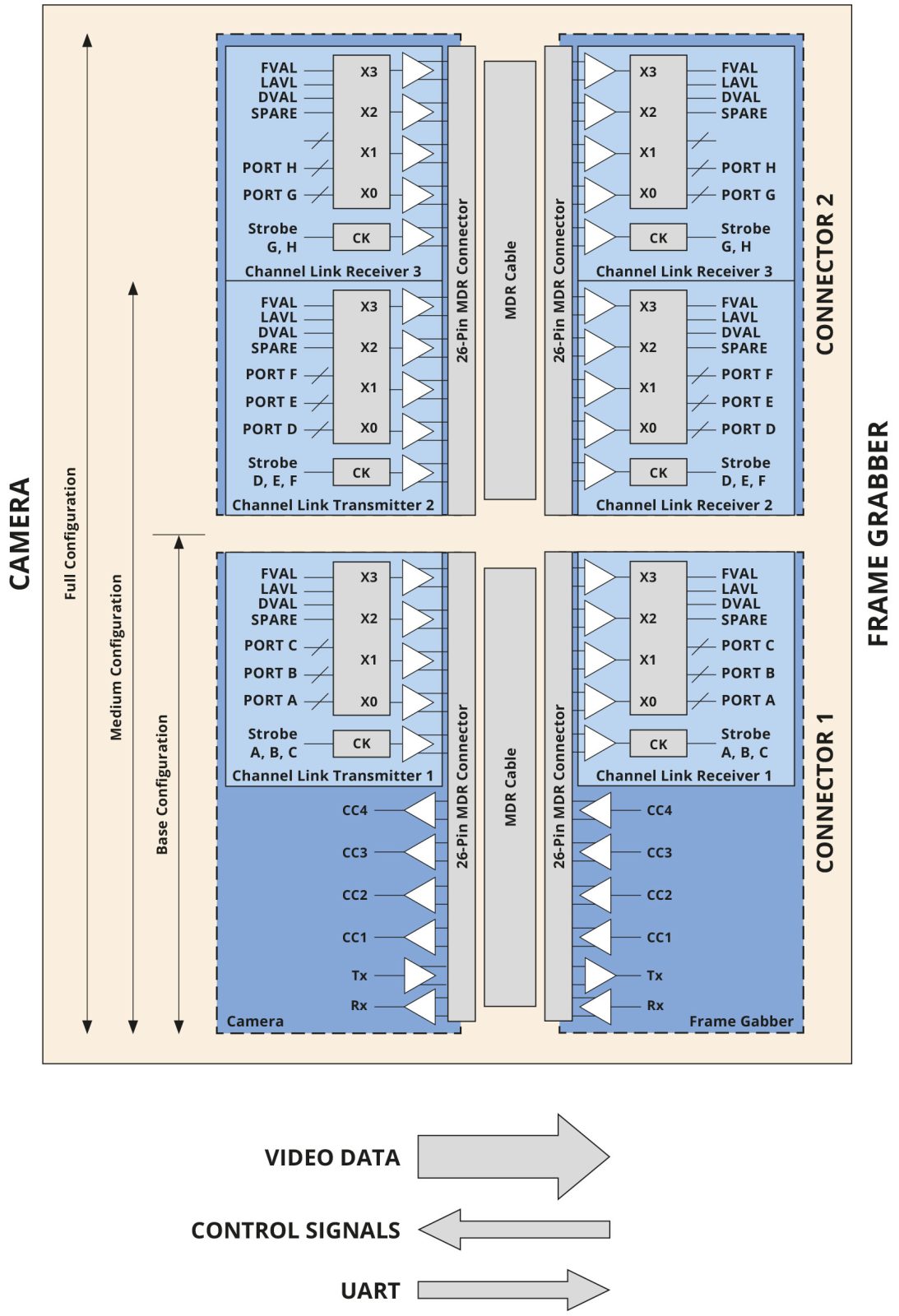
Base configuration
The “Base” Camera Link configuration carries signals over a single connector/cable. The cable carries 5 LVDS signals for video data streaming (24 bits of data + 4 framings/enable bits), 4 LVDS control signals and 2 LVDS for asynchronous serial communication (UART).
The max data throughput is 2.04 Gbps (255 MBps).
Medium/Full configuration
In these configurations, a second connector/cable is added.
In “Medium” configuration this provides 24 bits for additional video
data and the same 4 framings/enable bits as in “Base” configuration.
This yields a 48-bit data path capable of throughput up to 4.08 Gbps (510 MBps).
In “Full” configuration another 16 bits are added, resulting in a 64-bit data path that can carry 5.44 Gbps (680 MBps).
Deca configuration (80-bit variant – extended full)
The other 16 bits for video data are added, eliminating redundant control signals and taking advantage of unused wires. This yields an 80-bit data path capable of throughput up to 6.80 Gbps (850 MBps).
In all mode of operations we can identify 3 main communication channels:
- A video data streaming channel. As seen above this requires several wires in order to maximize the total bandwidth.
- An asynchronous serial communication (UART, seen as a virtual “COM port” from the host PC) which is used to set/get parameters of the camera (i.e. exposure, gain, bit depth…).
- 4 general purpose control signals which can be used for different functions, for example, to trigger the camera (named CC1, CC2, CC3, and CC4).
MODES OF OPERATION
In order to correctly receive and interpret the stream of video data, the camera and framegrabber must be configured in a coherent way. Image width and height, bit depth, pixel format, read out “taps”, connection speed (clock) and camera link modes need to be correctly configured in both devices. Failing to do so leads to artifacts and useless images.
The framegrabber is configured by means of a configuration file that contains all the parameters relative to the specific camera we want to communicate with. Configuration files are vendor-specific (framegrabber) and can have different formats. Usually, they’re text files that can be opened with any text editor.
Framegrabber vendors provide configuration files templates for each camera mode of operation.
A mode of operation describes the way the camera is controlled and how the data are sent to the framegrabber.
For example, Euresys (www.euresys.com) lists the following modes of operation for their CameraLink framegrabbers:
Area scan cameras
Short name |
Expose |
Readout |
Description |
PxxSC |
INTCTL |
INTCTL |
Synchronous progressive scan, camera-controlled exposure (free-run with fixed exposure controlled by camera) |
PxxRC |
PLSTRG |
INTCTL |
Asynchronous progressive scan, camera-controlled exposure (triggered with fixed exposure controlled by camera) |
PxxRG |
WIDTH |
INTCTL |
Asynchronous progressive scan, grabber-controlled exposure (triggered with exposure controlled by trigger-width) |
Line scan cameras
Short name |
Expose |
Readout |
Description |
LxxxxSP |
INTPRM |
INTCTL |
Free-running or camera-controlled line rate Permanent exposure or disabled electronic shutter No control line |
LxxxxSC |
INTCTL |
INTCTL |
Free-running or camera-controlled line rate Camera-controlled exposure with electronic shutter Single control line |
LxxxxRP |
INTPRM |
PLSTRG |
Grabber-controlled camera line rate and exposure Permanent exposure or disabled electronic shutter Single control line |
LxxxxRC |
PLSTRG |
INTCTL |
Grabber-controlled camera line rate camera controlled exposure Single control line |
LxxxxRG |
WIDTH |
INTCTL |
Grabber-controlled camera rate and exposure Camera-controlled exposure with electronic shutter Single control line |
LxxxxRG2 |
PLSTRG |
PLSTRG |
Grabber-controlled camera rate and exposure Camera-controlled exposure with electronic shutter Two control lines |